




PIR boards in industrial walls: insulation zones, fixings and moisture
PIR insulation
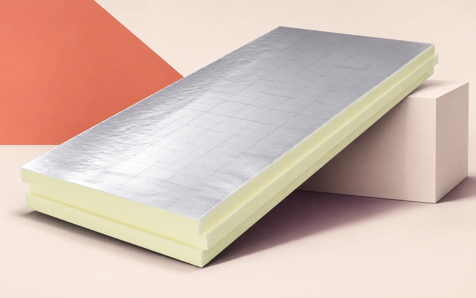
PIR insulation can be useful where wall thickness is restricted. In a large building, choose the board to suit the frame, external finish and conditions in each zone. Thermal conductivity alone cannot establish whether a board fits the wall design. A continuous layer of PIR outside the wall can reduce thermal bridging across the structure. Columns and rails form repeated junctions, changing both the heat-flow path and the positions available for fixings. Set out the insulation in relation to the structural grid and draw the junctions where it crosses the frame or meets the rest of the façade.
In this article
Keeping the wall insulation continuous
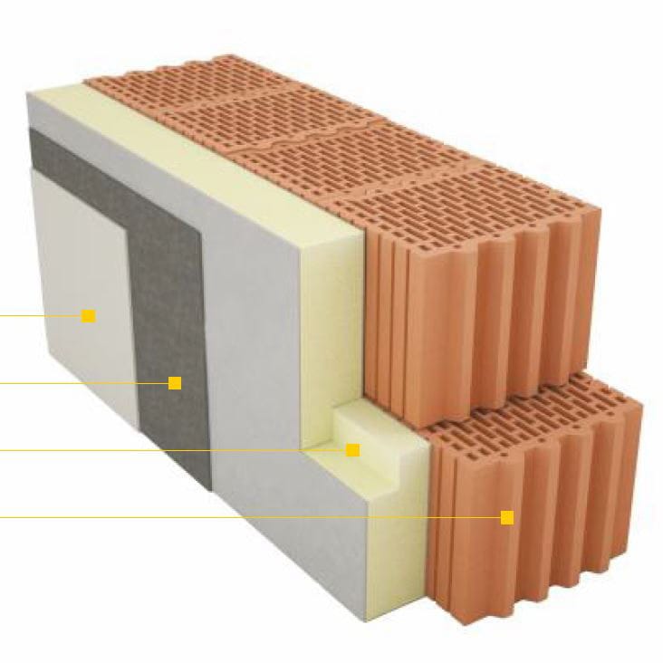
Correctly routed continuous insulation can reduce some of the effects of the frame. Detail penetrations and joints, and check a complete repeating structural bay. Insulation performance between frame members alone does not describe the whole wall.
PIR beneath render in an ETICS assembly
An external thermal insulation composite system (ETICS) comprises insulation, adhesive, fixings, a reinforced base coat and the finish. In a rendered zone, select a board intended for that particular system.
Where a façade changes from render to another finish, check the board and accessories on each side. Detail the terminations at the boundary. Confirm suitability before specifying the same board for both applications. List and order the zones separately where needed. This retains the space advantage of PIR while meeting the requirements of each finish.
Ventilated façades and cavity walls
A ventilated façade has a cavity behind the cladding. The subframe carries the cladding weight and wind loads. In a masonry cavity wall, details include the ties between leaves. Show the fixing arrangement for the selected system on the insulation drawing.
Coordinate the subframe with the insulation before ordering board sizes. The safe spacing of brackets depends on façade construction and loading. Brackets create cuts and joints that repeat across the elevation. Check their effect on thermal performance and airtightness after setting out the support positions. Coordinating the trades on the drawing avoids having to resolve repeated clashes from the scaffold.
Vapour movement and drying potential
When assessing moisture, distinguish diffusion through materials from moist air leaking through a gap. A faced board may have high vapour resistance, yet air from the hall can still enter the wall through a leaky floor junction.
Mark the extent of a humid zone on the wall section, including floor junctions. Internal conditions may require different layer properties or sealing details in that zone. Follow the boundary through the floor and roof connections. The drawings should show how the enclosure surrounds the entire space with that particular use.
Reveals, plinths and roof junctions
At a door guide rail, measure from the structural edge to the proposed reveal lining. There must be room for the insulation and the specified fixing. Check the detail together with the threshold and lintel before ordering PIR board sizes.
A large industrial door has long junctions and may operate frequently. Insulating its reveals helps maintain the thermal performance of the wall, while the door fixings must carry the forces generated by its operation. Separate the structural support from the thermal infill on the drawing. Thin PIR can fit a restricted reveal if the board is suitable for the detail.
Internal insulation during refurbishment
If the external façade is to stay in place, survey the wall from inside the hall before selecting internal PIR boards. Mark cabinets, cables and penetrations. Allow for how the masonry will dry after insulation and how to seal around services.
Keep access to important service connections when planning the new lining. Identify the equipment to be retained, relocated or kept accessible, and detail continuous seals around it. Mapping these functions by zone reduces the risk of concealing an active installation that will later need inspection.
Measuring junction lengths around openings
Six identical windows illustrate the scale of work around openings. For a 1.4 m wide by 1.6 m high window, the horizontal edges total 2.8 m and the vertical ones 3.2 m. Across six openings, that gives 36 m of façade junctions. Measure lintels, sills and side reveals separately because their finishing details differ. Edge lengths help quantify the work. Assess thermal bridges from the actual sections.

Free quote
What to include in your enquiry
Tell us how you plan to use the material, the dimensions and the quantity you need. Include the thickness, grade or variant name, along with the delivery town or your preferred collection branch. For a specific product, add its name or a link to the product page. We will reply to the email address you provide to discuss availability and the terms of your order.
Read next
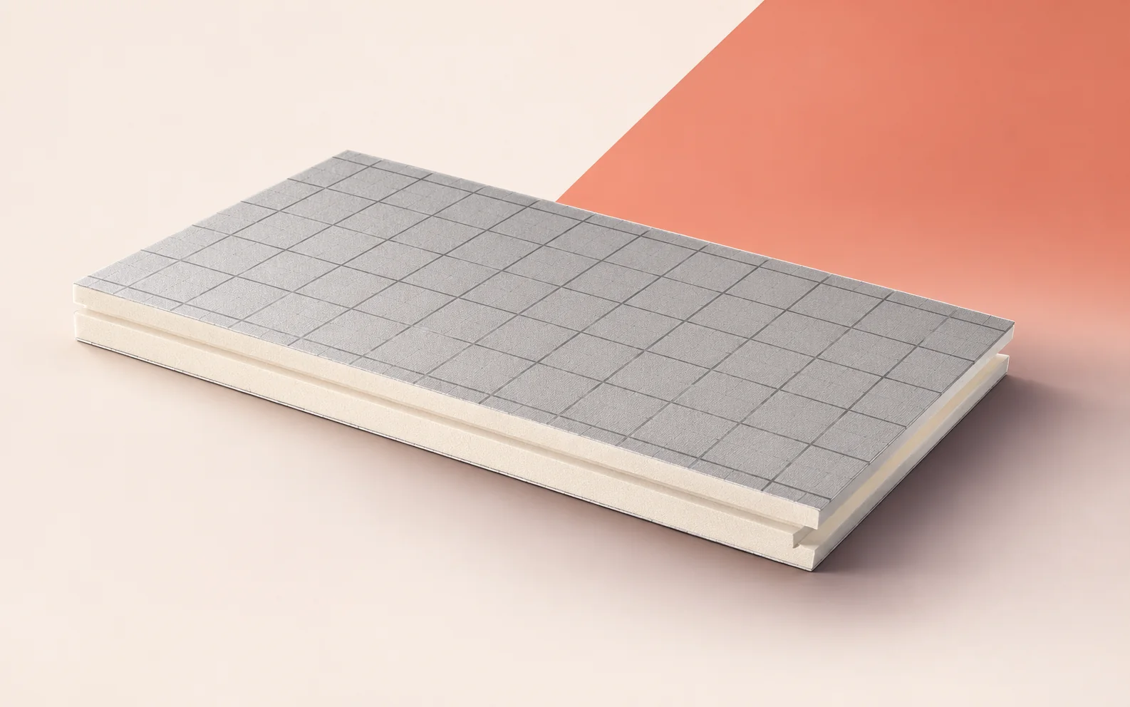
How can a site team check the continuity of IDELCO α-therm WALL insulation on a warehouse or office façade? Select a full…
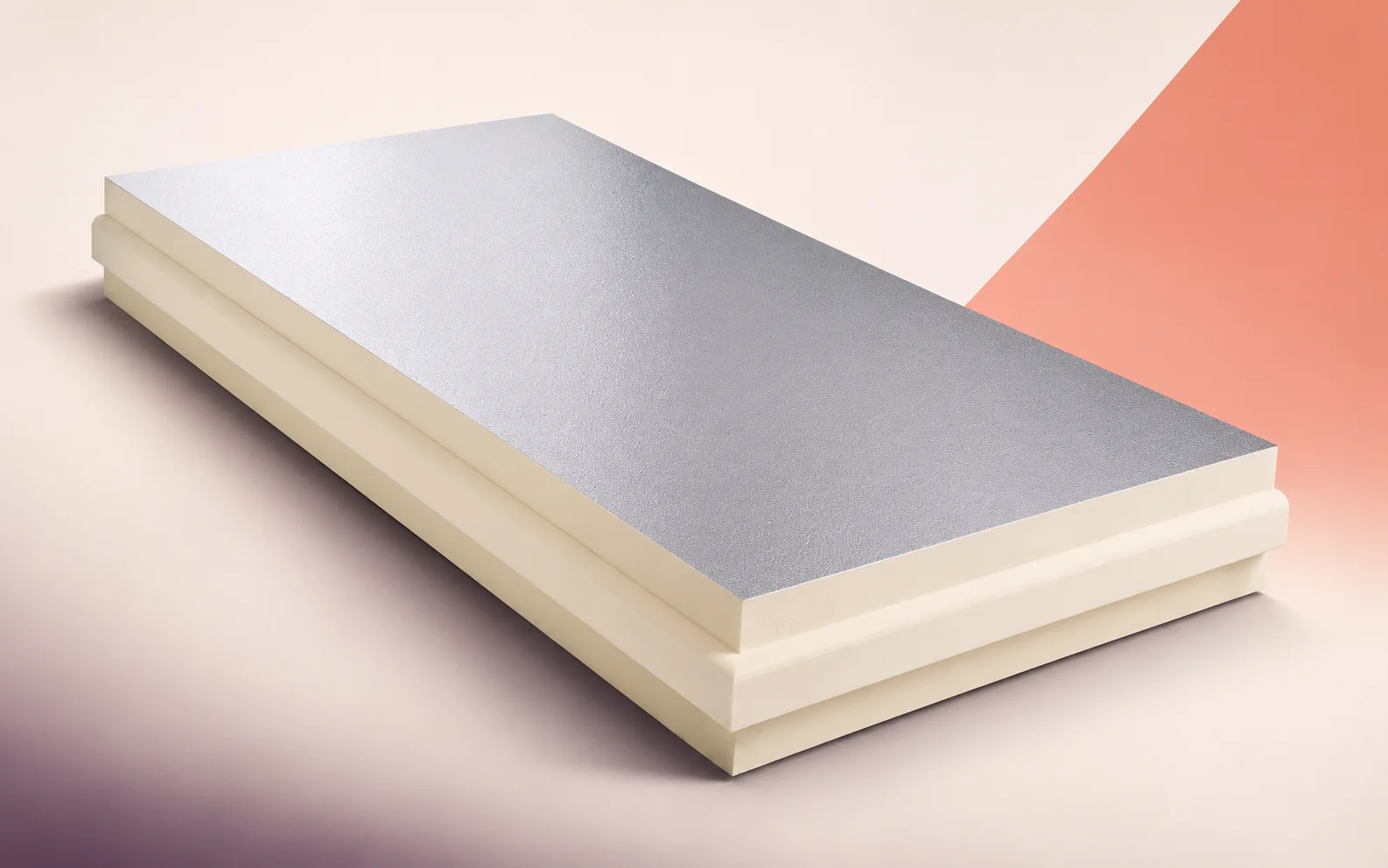
Above-rafter insulation with Recticel Powerroof allows much of a refurbishment to be carried out from outside. Whether the attic lining can stay…
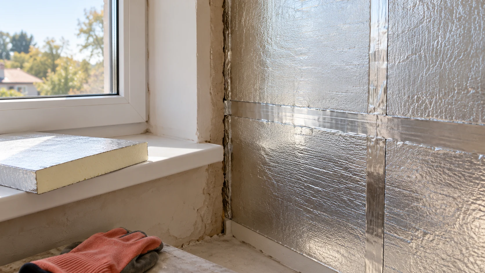
An aluminium facing restricts vapour diffusion through a board, but the insulation also depends on its connections to floors, ceilings, windows and…
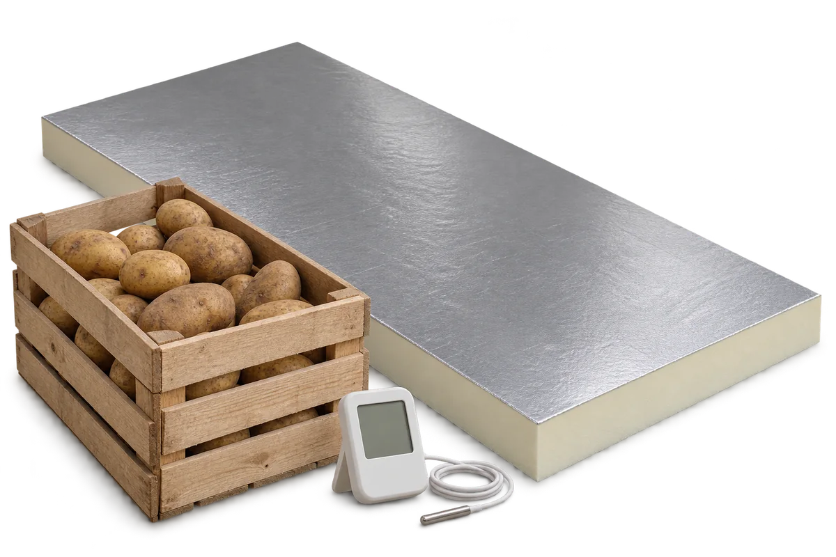
The withdrawal of a sprout suppressant formerly used in potato stores changed storage practices. Residues in older buildings need separate assessment even…
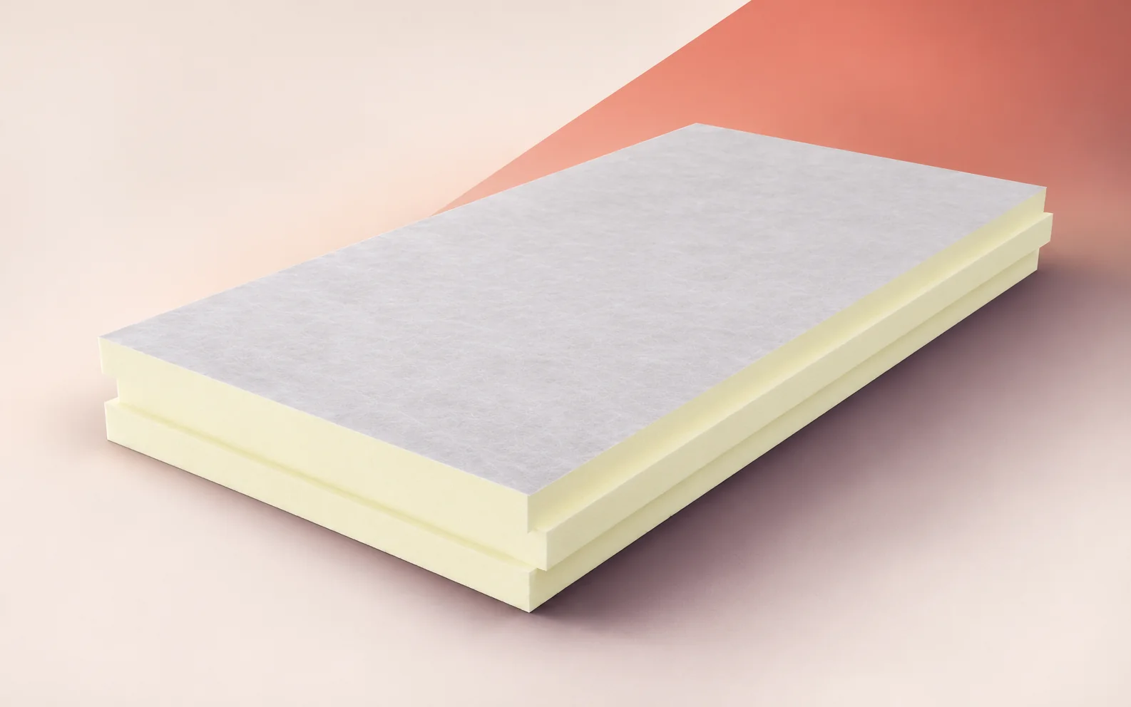
On a flat industrial roof, start by establishing how the waterproofing will be attached. The termPIR WS board has a rigid PIR…
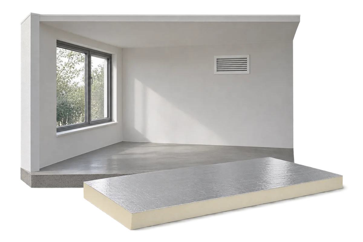
A damp basement should not be assessed in the same way as a heated upstairs room. In summer, warm air entering a…

A cold surface, poor ventilation, rain penetrating the façade and a leaking pipe can leave similar marks. Several causes can coexist. Before…
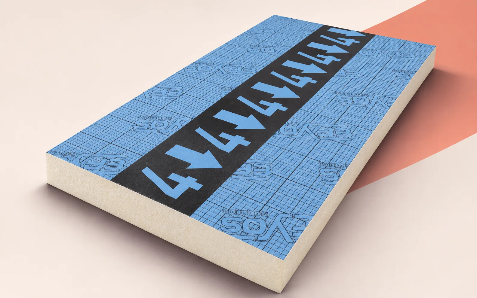
Order EFYOS BLUE SMART A boards from the falls plan. Start at one outlet. Mark its catchment boundary, outlet level, high points…