



Joining swissporPIR Alu boards across a large roof area
PIR insulation
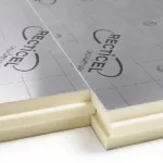
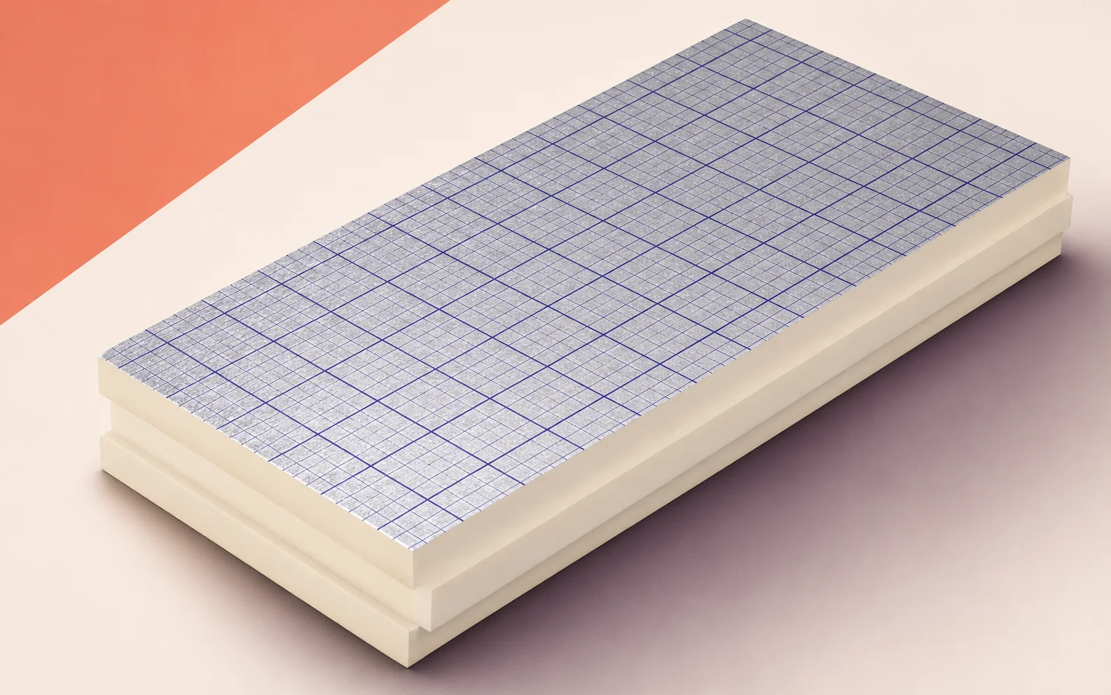
On a long roof, joint alignment is particularly easy to check where two runs of swissporPIR Alu pass either side of a rooflight and meet again beyond its kerb. If the runs start at different angles, a wedge-shaped gap appears on the far side. Before cutting, establish a reference line across the bay, draw the joints and check the edge orientation on the first pair of boards. The manufacturer offers square FIT/GK, rebated LAP/SF and tongue-and-groove TAG/NuF edges. Each affects how cut pieces fit. A two-layer build-up also needs a separate joint layout for the upper course.
In this guide
Use two boards to establish laying direction
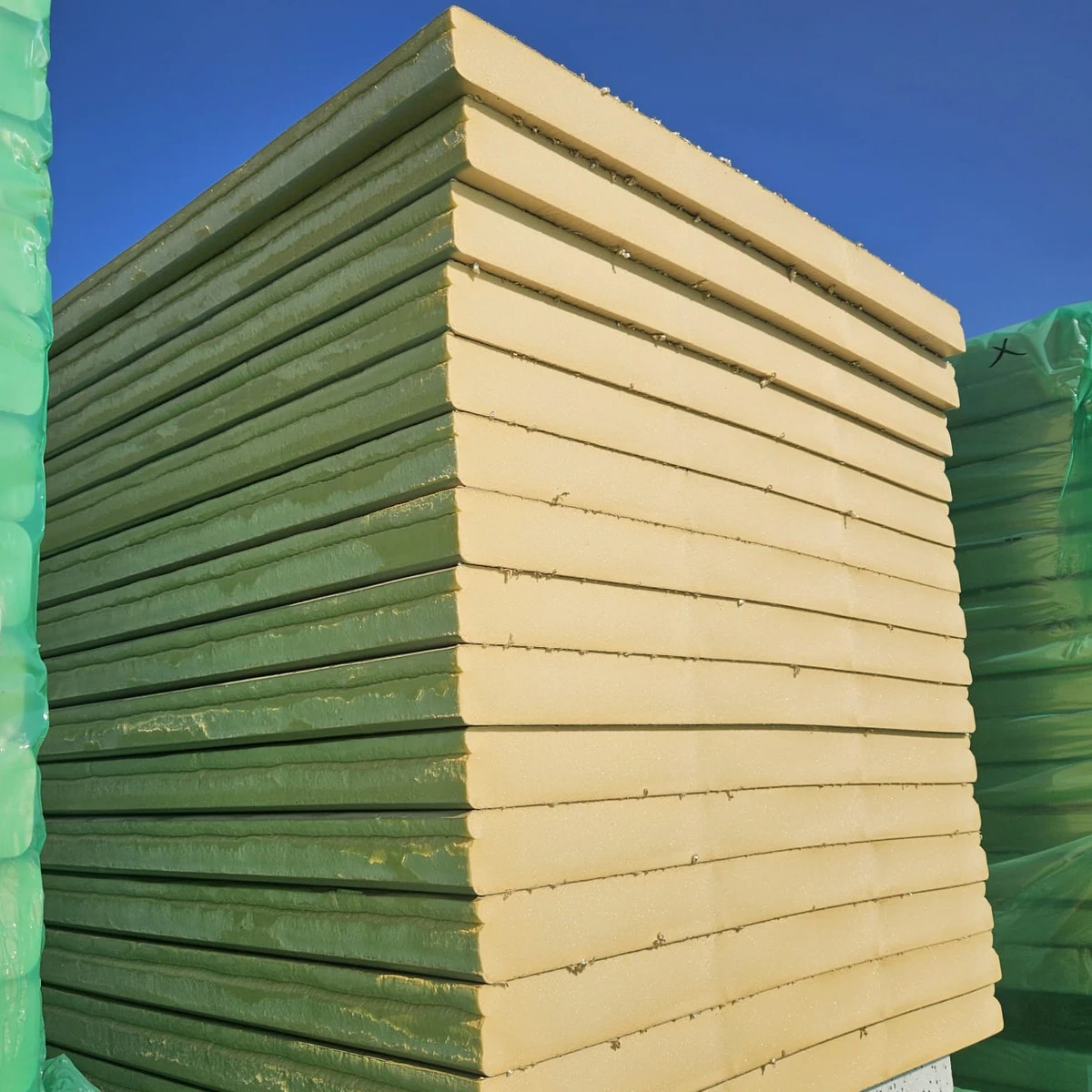
Bring two boards together on a level surface. With LAP, the upper lip of one rebate covers the lower lip of the next. TAG has a tongue that enters a groove, while FIT brings two flat edges together. Mark the direction in which boards are added with an arrow on the roof plan.
Why do rows drift apart at openings?
Before splitting the run at a rooflight, transfer the reference line to the far side. Check the distance from the line to the board edges on both sides of the kerb. A misaligned first board can still be adjusted without lifting the entire strip.
The manufacturer declares a thermal conductivity of 0.022 W/(m·K) for swissporPIR Alu. A visible gap between boards is a local break in the insulation. Before covering it, determine whether the cause is a skewed row, a broken edge or debris caught in the profile.
Which edge should survive the cut?
At the kerb, mark the side that will face the adjacent full board. Retain the matching factory profile on that edge. Measure the cut in its actual location as an existing kerb may be out of square.
Write the dimensions and surviving edge orientation on each offcut. Two rectangles of equal width may have rebates facing opposite ways. A trial fit against the adjoining board will show whether a piece can be used at the next opening.
How to set out the second layer
Before concealing the lower course, sketch its joints with dimensions from a fixed point. On a second drawing, stagger the upper boards so that joints in the two layers do not coincide. Check the pattern where the run divides around an opening as well.
At the end of each stage, photograph both layers where part of the lower one is still exposed. The image records the laying direction and joint offset. Where the design calls for joint tape, apply it after checking that the cores and facings fit together.
Supporting a short cut piece
On a profiled steel deck, check where the end of a cut board falls relative to the top flanges. Engaging the tongue and groove does not provide a bearing. The support detail must account for board thickness, deck profile and the position of the cut edge.
If the drawing leaves a narrow unsupported strip at the opening, review the cutting plan with the designer before laying further bays. Moving the start of a row can allow larger pieces on both sides of the kerb. Recheck the joint positions in the second layer after the change.
Coverage in the order schedule
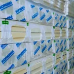
Ask the supplier for coverage per pack for the specified format, edge and thickness. Add boards needed for the cutting list to the count of full boards laid intact. Confirm profiled-edge availability particularly when ordering thin insulation.
Split the list into bays between the building grid lines. Record the number and edge type of pieces carried forward into the next bay. The first bay then gives a measured basis for the allowance, avoiding repeated waste allowances for the same piece at successive rooflights.
Inspecting the row beyond the rooflight
Beyond the first rooflight, place a whole board against the two converging runs and compare its edge with the reference line. Inspect the joint along its length and the bearing at both ends. Once this junction fits, the cutting layout can be repeated at subsequent rooflights.
Free quote
What to include in your enquiry
Tell us how you plan to use the material, the dimensions and the quantity you need. Include the thickness, grade or variant name, along with the delivery town or your preferred collection branch. For a specific product, add its name or a link to the product page. We will reply to the email address you provide to discuss availability and the terms of your order.
Read next
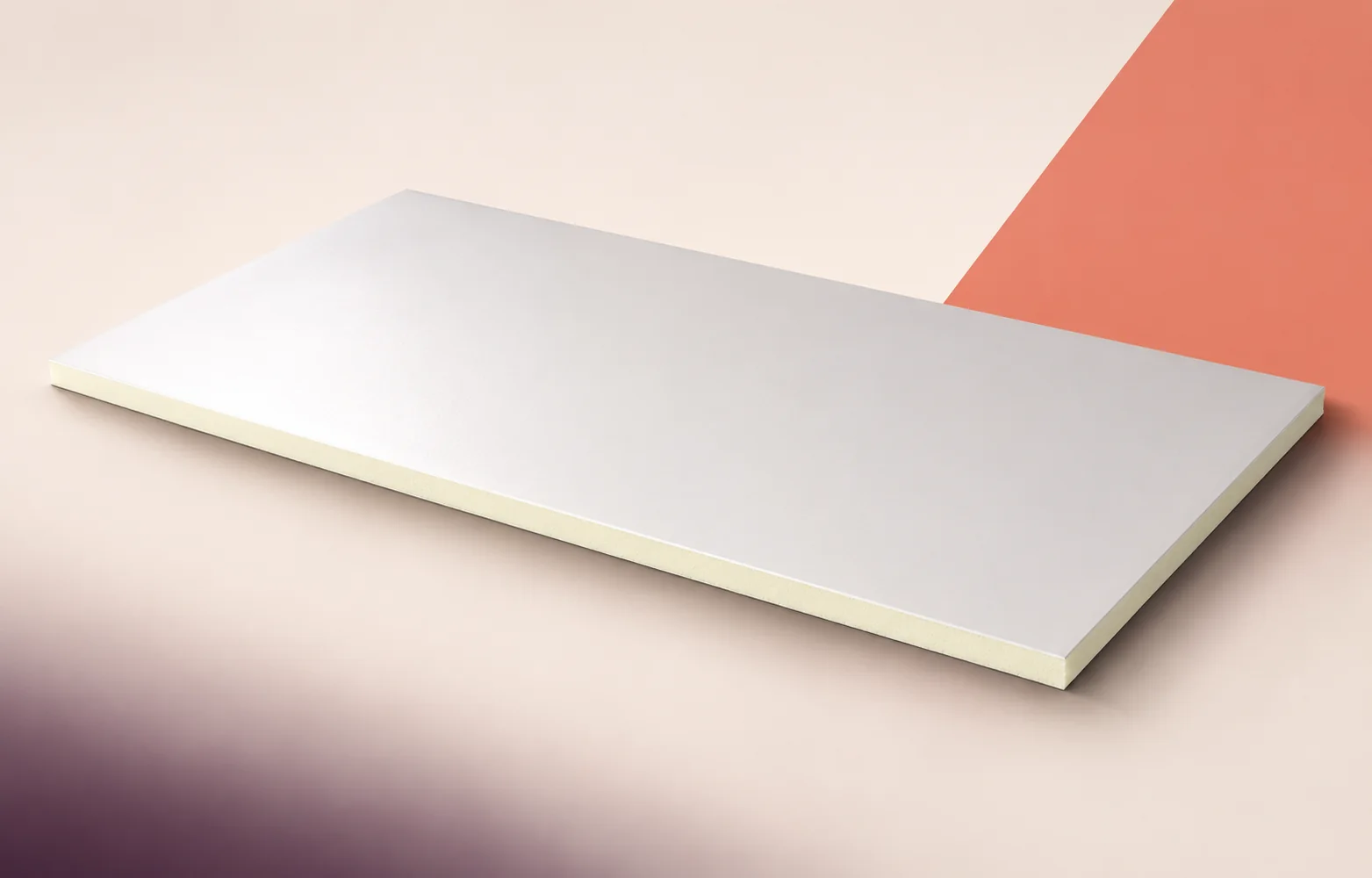
Three measurements matter when ordering IDELCO AGRO+ ceiling boards for a livestock building or farm store: the length of the area to…
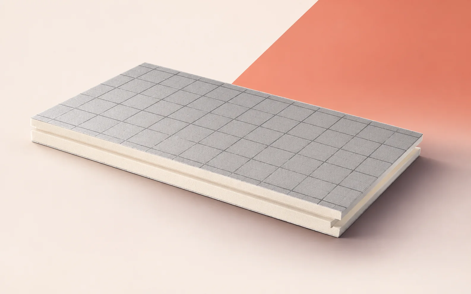
How can a site team check the continuity of IDELCO α-therm WALL insulation on a warehouse or office façade? Select a full…
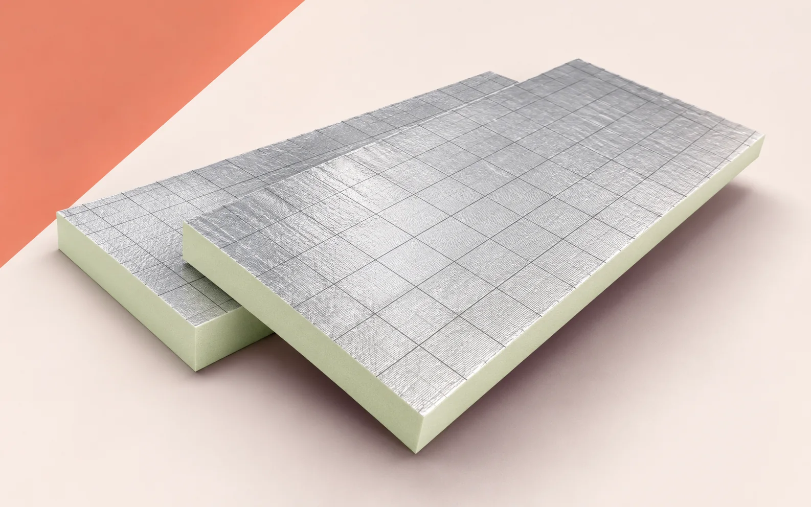
An office and an adjoining plant room can have the same finished floor level even though the floor beneath a heavy cabinet…
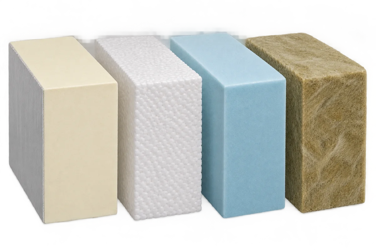
Different insulation materials can work together in one building element when each solves a specific problem. PIR can keep the build-up thin,…
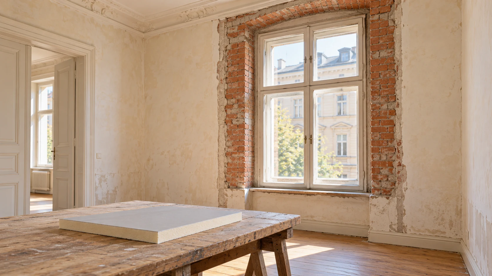
When a historic façade must be preserved, internal insulation may be an option. First establish how the walls and floors are built.…
A calculator result is useful only when you know what was modelled. The same wall can give a different result if indoor…
Start with thermal resistance, R, to compare two layers performing the same job. The result depends on the conductivity of the specific…
Roof works across a housing estate can be tendered together, but each block needs its own survey. The height of a roof…