




IDELCO α-therm WALL in cavity walls: keeping the PIR layer continuous
PIR insulation
How can a site team check the continuity of IDELCO α-therm WALL insulation on a warehouse or office façade? Select a full structural bay that includes the plinth, a window and the lintel. Plot the actual wall tie positions and the outlines of the 1200 × 600 mm PIR boards on an elevation. This reveals where a tongue-and-groove joint meets a cut edge. Inspect those joints, cavity width and drainage below the window before laying the outer leaf. Once the masonry goes up, photographs may be the only record of concealed details.
In this guide
The wall in section and elevation
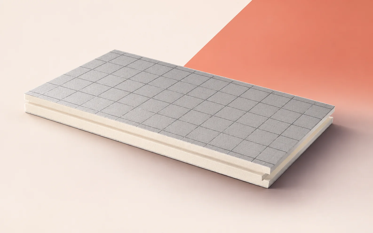
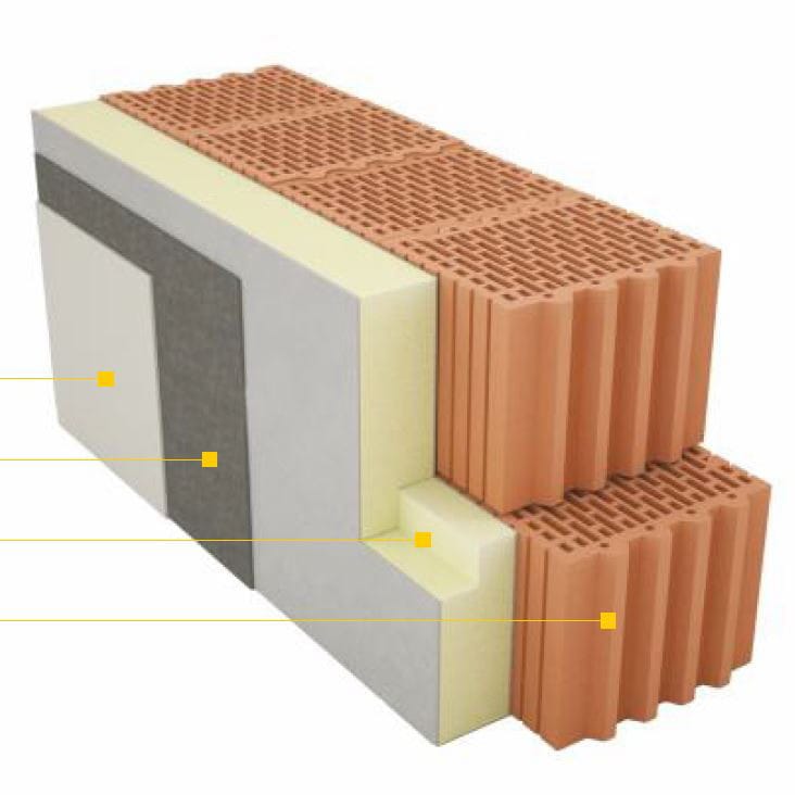
In section, identify the structural inner leaf, PIR with aluminium laminate on both faces, the specified cavity and the outer leaf. Show ties and cladding supports on the elevation. Overlaying the two drawings reveals where cut insulation will meet a bracket or opening.
How much space does the insulation take up?
For a 100 mm board, the manufacturer gives a thermal resistance of 4.50 m²K/W and thermal conductivity of 0.022 W/(m·K). Calculating the wall U-value also requires the other layers and details of the ties. Heat flow at the lintel and plinth junction needs separate consideration.
With a fixed distance between masonry leaves, a thicker board reduces the space left for the cavity. Compare the site measurement with the design section, especially where the backing is uneven. Agree any change in thickness before ordering ties, supports and sills for the whole façade.
Cut boards between wall ties
Set out the first course on the drawing against the ties already in the wall. Where a tie falls close to a board joint, check the fit specified in the detail. Moving or bending the tie on site would change the geometry of the connection between masonry leaves.
Mark the tongue or groove on each offcut intended for reuse. Two pieces of the same width may suit different reveals. Before concealment, inspect cut edges and check the fit against the backing and adjacent pieces against the detail drawing.
Where does water go below the sill?
Trace the drainage route in section from beneath the sill to the designed outlet. Check the flashing returns at both reveals. Photograph and identify the ends of the flashing while they are still visible, before the outer leaf conceals them.
The board facing is part of the insulation product. The flashing and cavity arrangement designed for this wall carries water out. As masonry work proceeds, check outlet openings and remove mortar droppings from the drainage path.
Reading the α-therm WALL data sheet
Two English-language manufacturer sheets for WALL give different minimum compressive stresses at 10% deformation: 120 and 150 kPa. Record the value confirmed for the supplied boards in the handover documents. Tie capacity and permissible support loads require separate data.
Both sheets list reaction-to-fire class F for the product. Retain the full name α-therm WALL in the wall specification. Results for a differently designated variant or for a tested assembly have their own scope of application.
Measuring quantities for repeated bays
A 1200 × 600 mm board has a nominal area of 0.72 m². Dividing net wall area by this figure gives a full-board equivalent. Refine the order by setting out pieces below windows, strips at floor edges and boards at the ends of courses.
Compare the cutting layouts for two consecutive bays. If a piece left at the right-hand reveal of the first bay fits the left-hand reveal of the next, put both locations on the same cutting list. Measure the corner bay separately before multiplying quantities across the elevation.
What does the next crew need?
Attach an overall elevation of the first bay, close-ups of the plinth and reveal, and a cavity measurement with its location marked. Identify which details repeat and where the dimensions change. The crew building the outer leaf then has a clear reference for the remaining bays.
Free quote
What to include in your enquiry
Tell us how you plan to use the material, the dimensions and the quantity you need. Include the thickness, grade or variant name, along with the delivery town or your preferred collection branch. For a specific product, add its name or a link to the product page. We will reply to the email address you provide to discuss availability and the terms of your order.
Read next
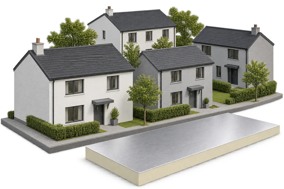
Roof works across a housing estate can be tendered together, but each block needs its own survey. The height of a roof…
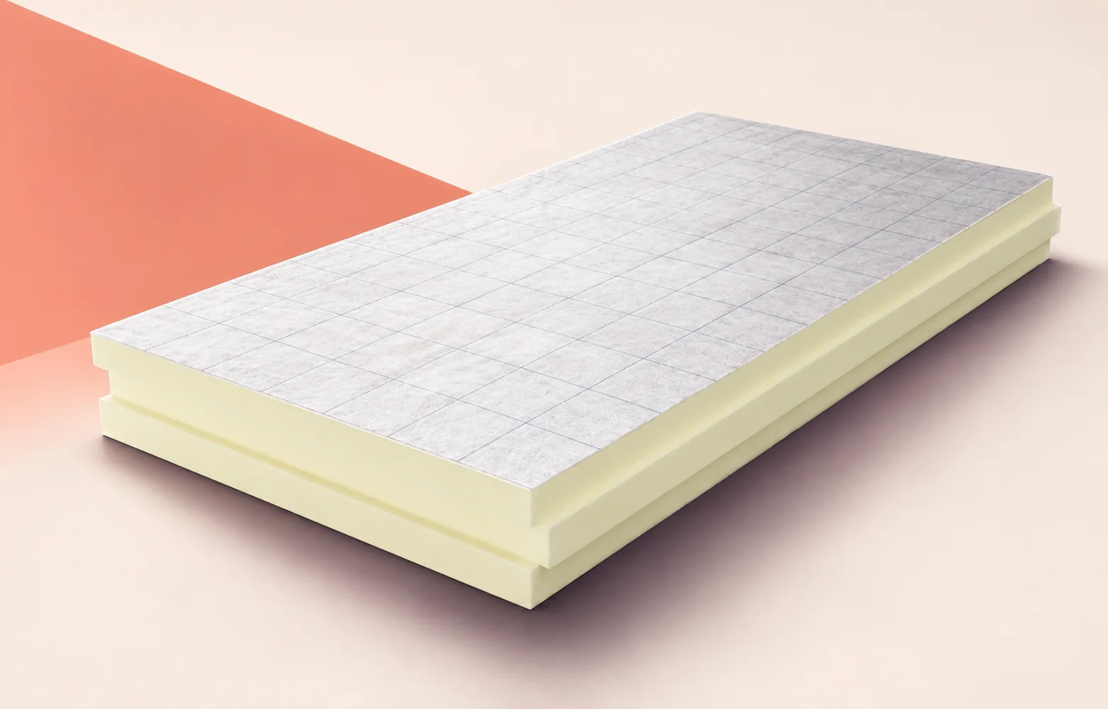
When refurbishing an industrial building with low door thresholds, measure the height from the substrate to finished floor level before choosing termPIR…
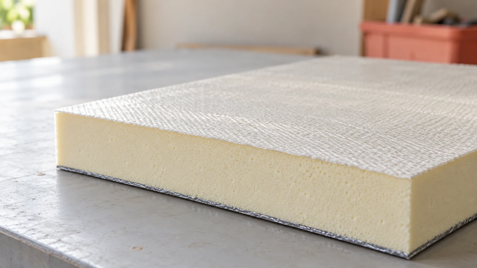
Glass-reinforced resin can form the inner facing of a PIR panel. It changes how that side of the enclosure is protected and…
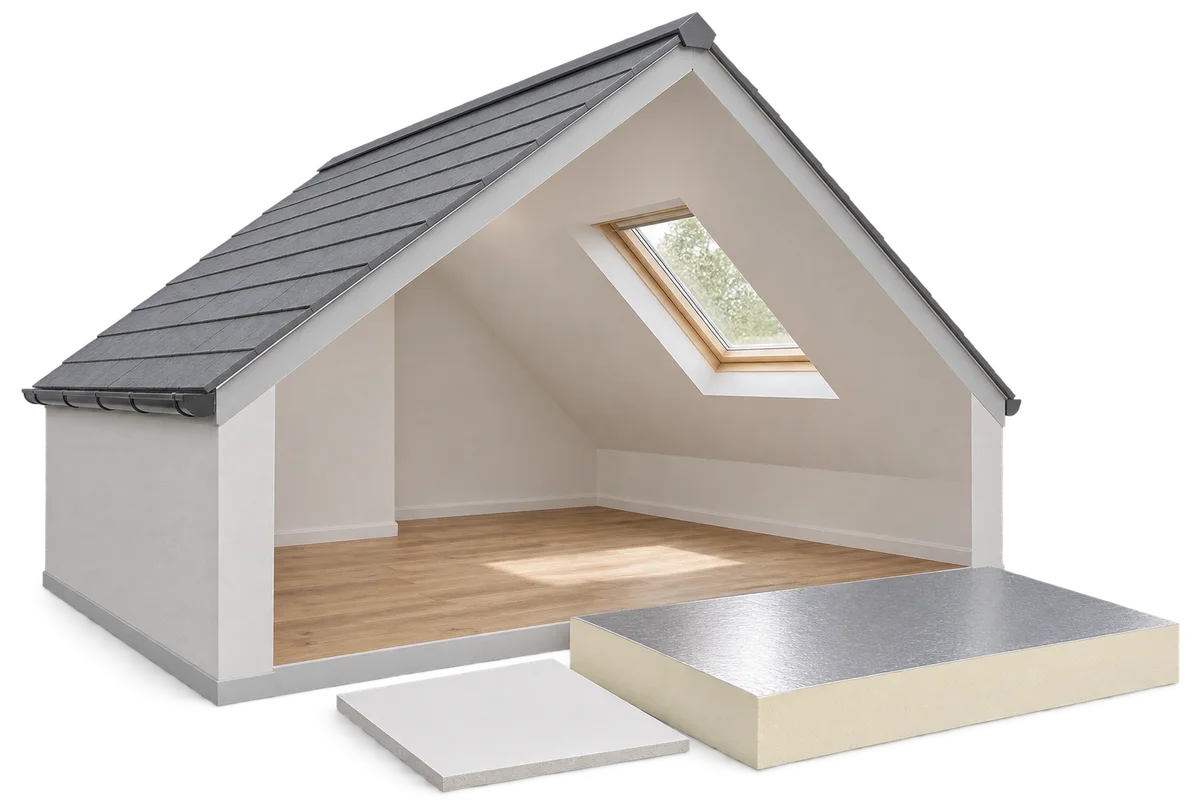
A loft fit-out starts well before the first plasterboard goes up. Inspect the roof, plan the insulation and establish how the layers…
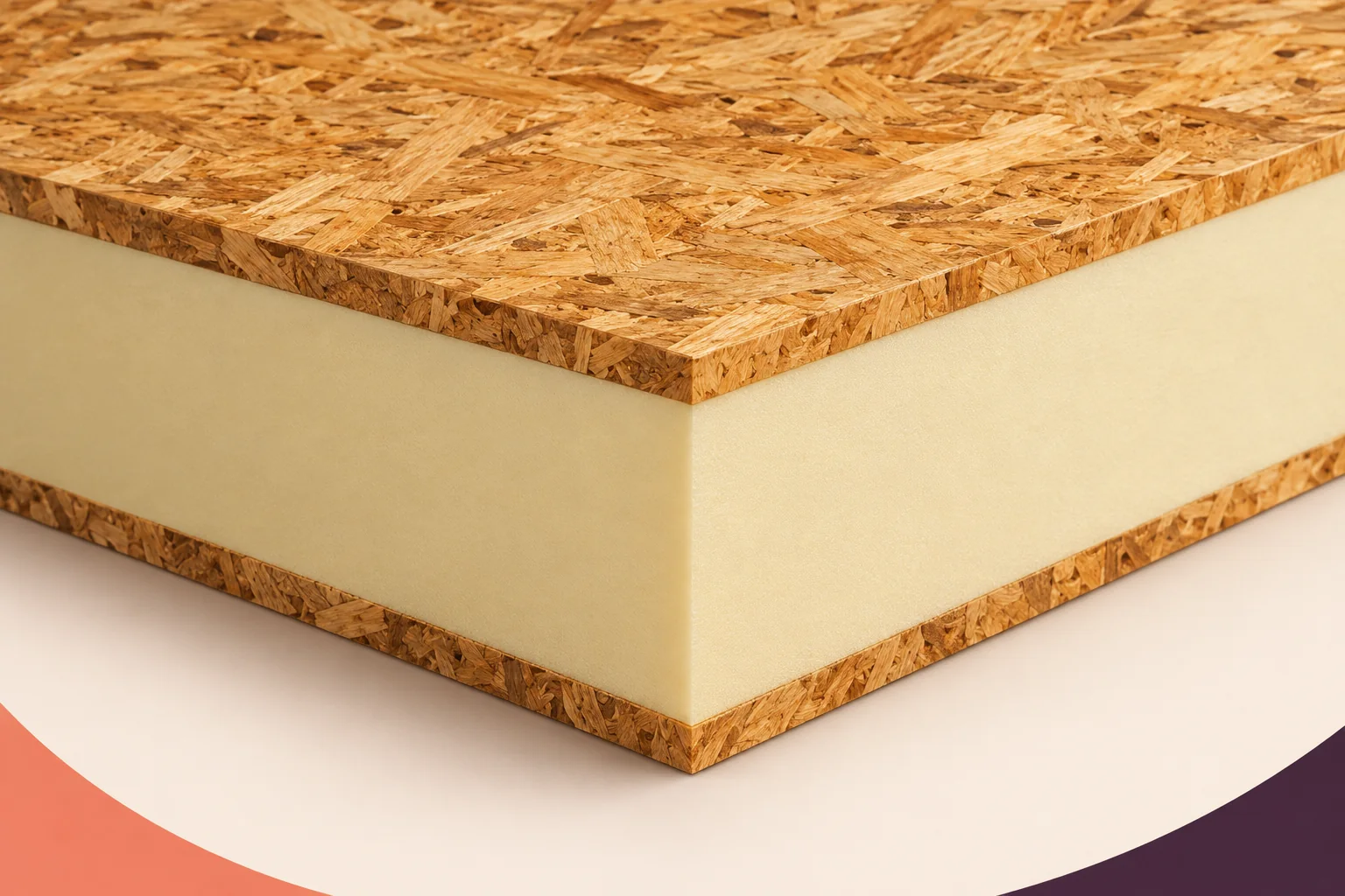
When comparing structural insulated panels, first identify what each quoted figure describes. Thermal conductivity, λ, belongs to a material. Thermal resistance, R,…
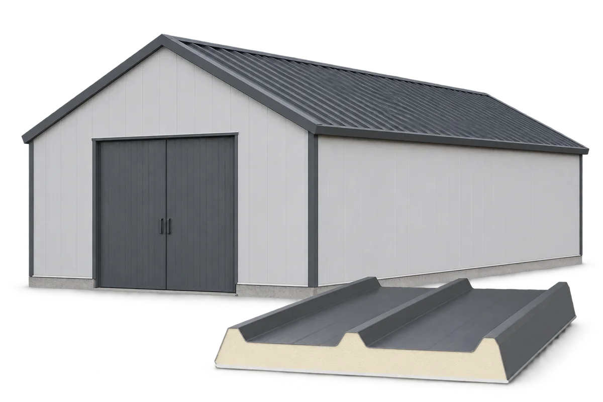
On the floor plan, mark the heated part of the workshop and trace the airflow through the produce store. That will help…
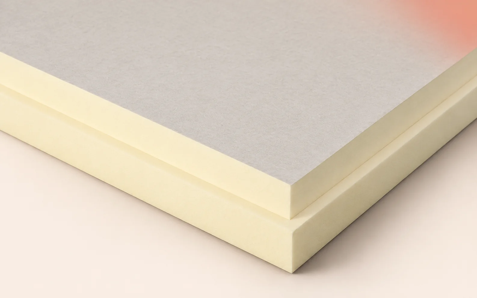
If a supplier offers an aluminium-faced board in place of BauderPIR M or MF, start with two questions. How will the layer’s…
When laying BauderPIR T, first set out the valley that will carry water to the outlet. Mark levels at both ends and…