



Thermano Roof beneath rooftop equipment. What does CS 200 kPa tell you?
PIR insulation
The foot of an air handling unit transfers weight to a small part of the roof. To assess Thermano Roof boards beneath it, the designer needs the reaction at each support, its contact area and the sequence of layers down to the structural deck. CS(10/Y)200 describes how the PIR board behaves in a compression test. Permanent loading also calls for data on deformation over time and the settlement the equipment base can tolerate. The example below shows how to calculate average contact pressure from installation data. Membrane protection, drainage and service access also influence the support layout.
In this guide
How to read CS and TR on the data sheet
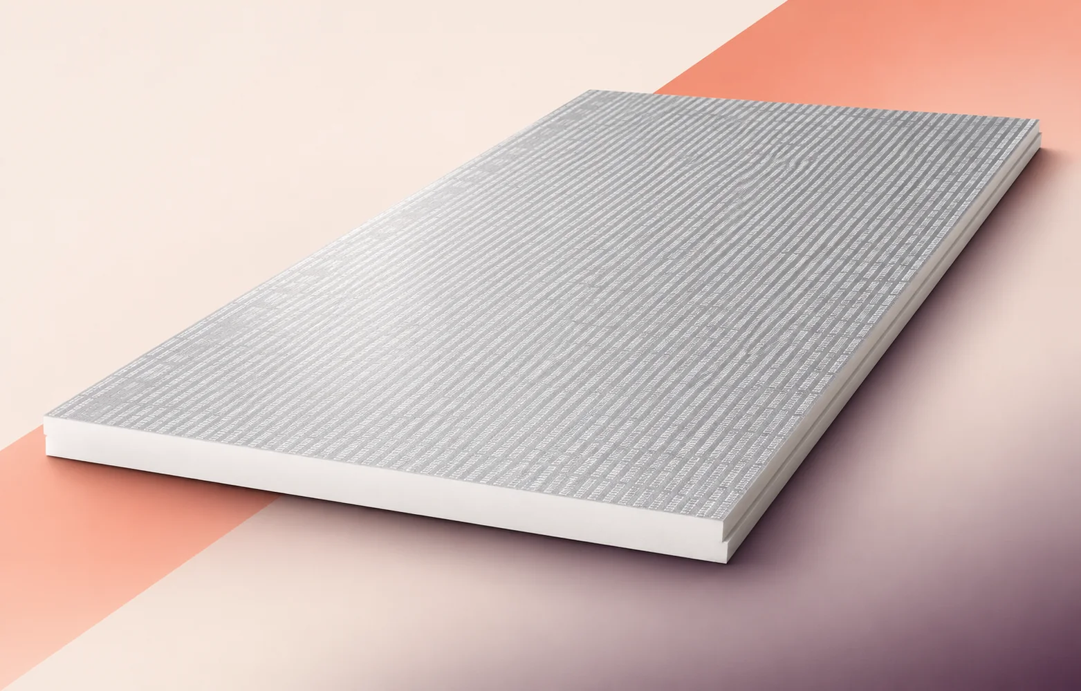
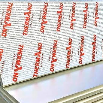
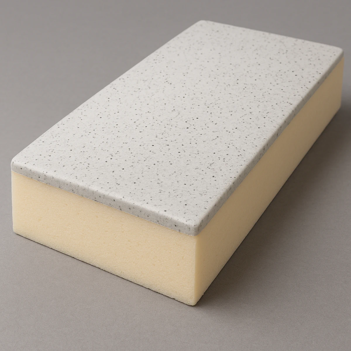
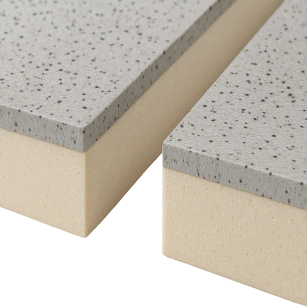
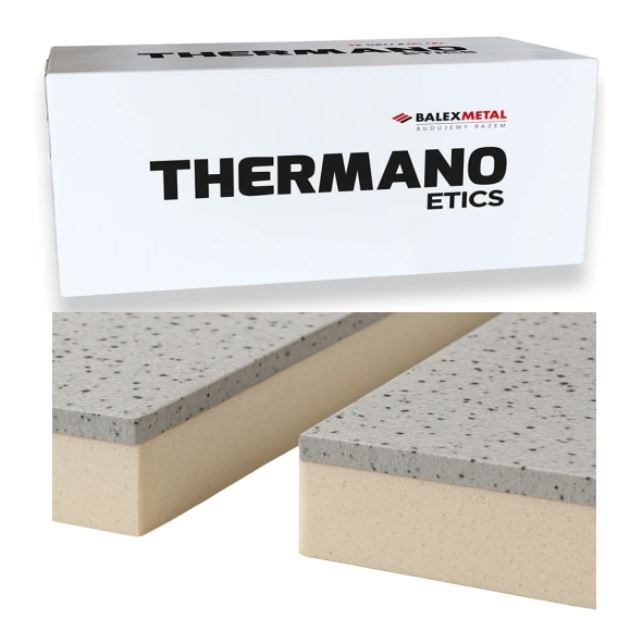
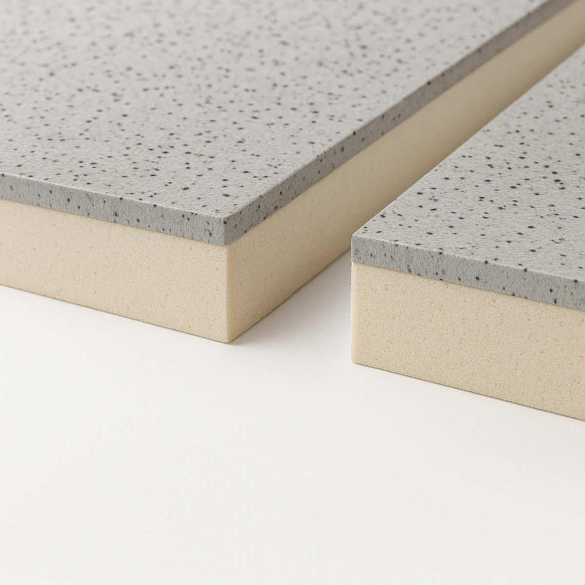
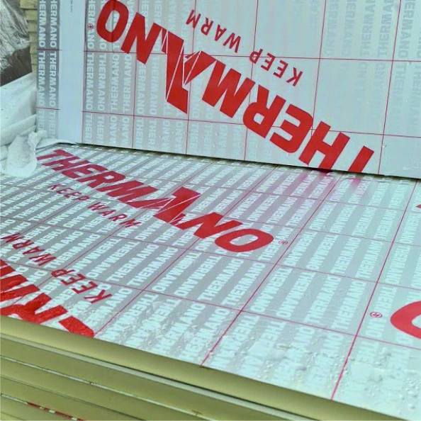
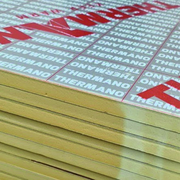
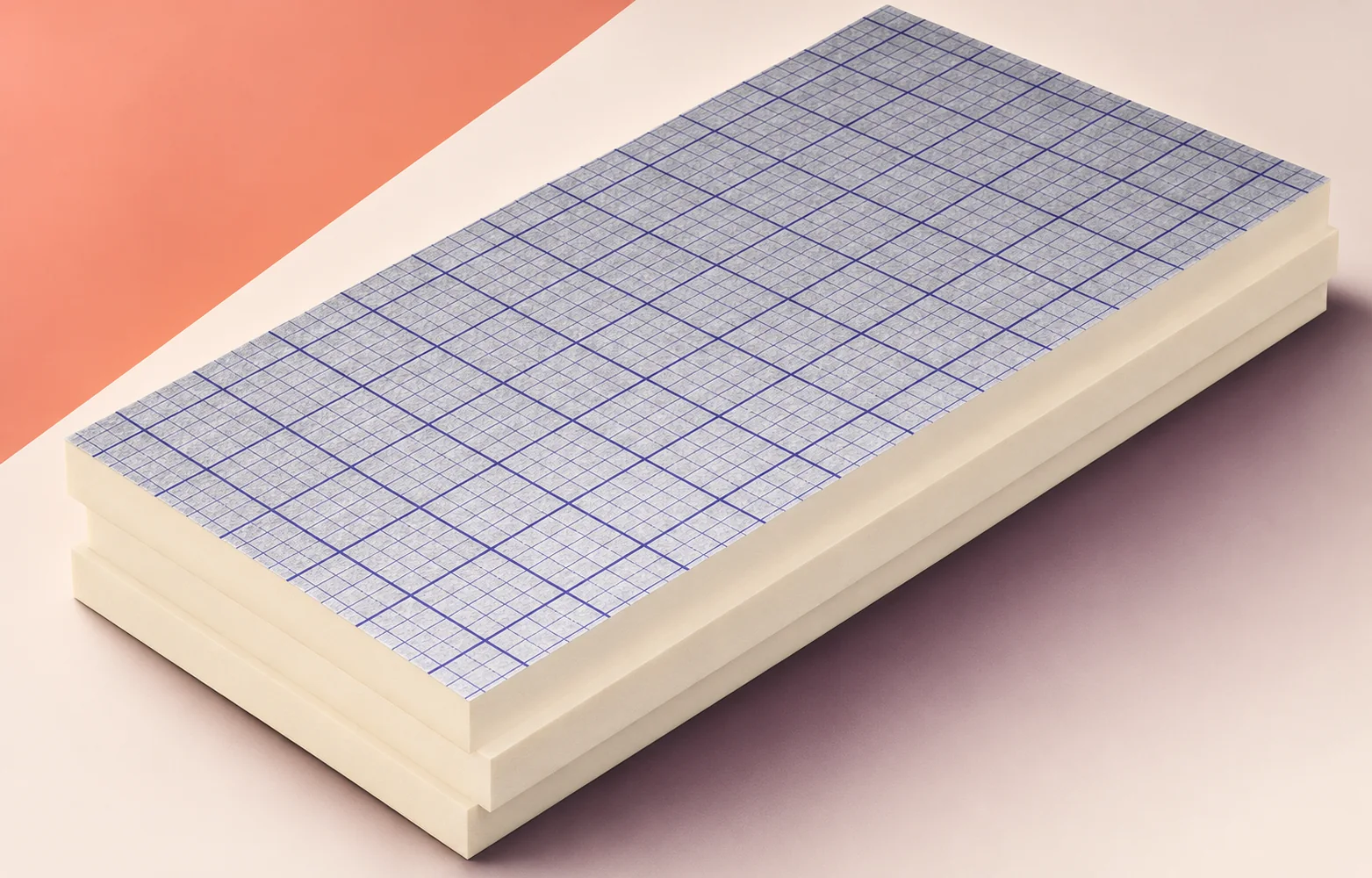
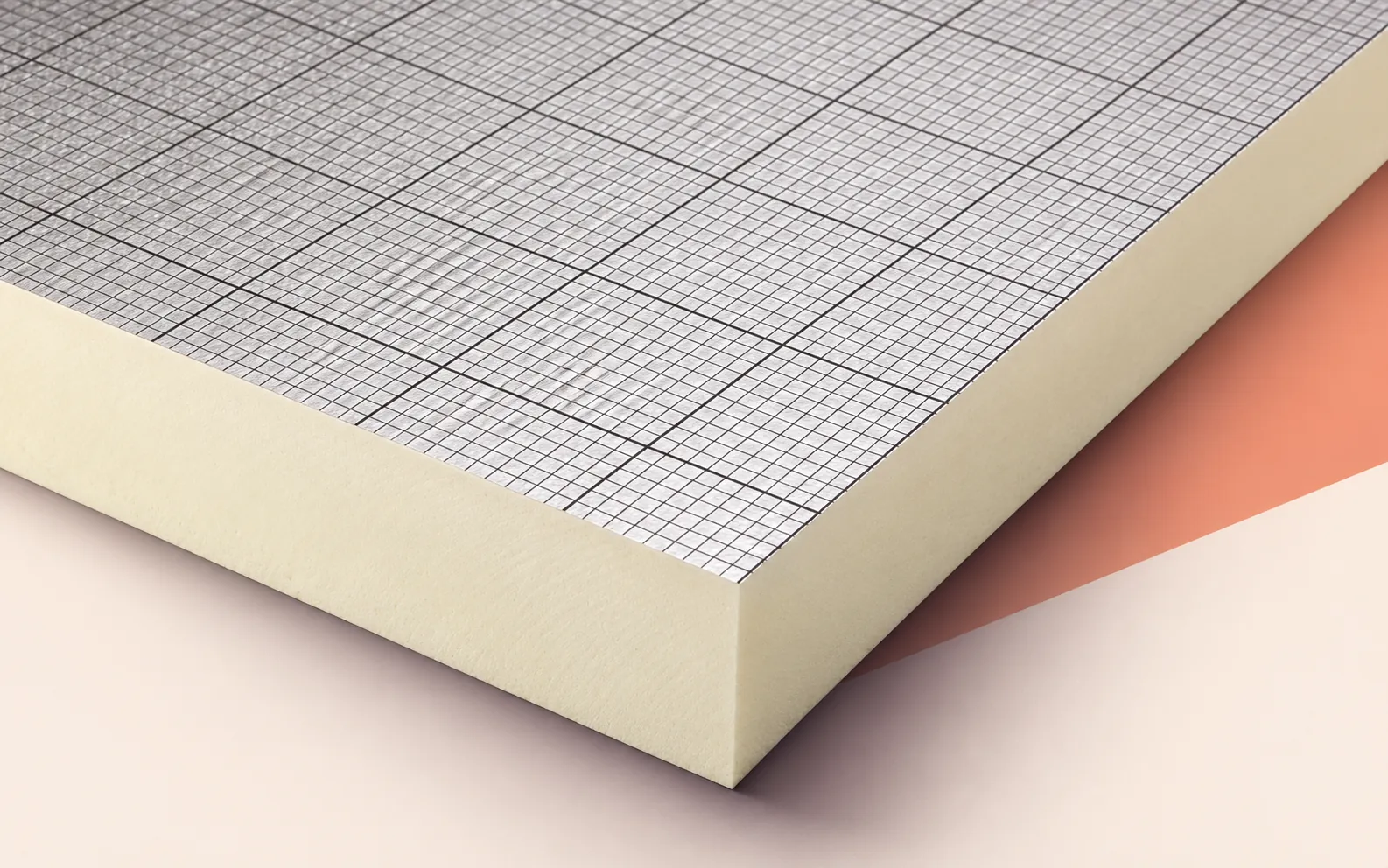
Thermano Roof is a rigid PIR board with a gas-tight, aluminium-containing multilayer facing on each side. In CS(10/Y)200, the number gives the declared compressive stress level in kilopascals at 10% relative deformation, or the compressive strength if reached earlier.
TR100 concerns a different loading condition. It indicates a tensile strength of at least 100 kPa perpendicular to the board faces. When specifying PV fixings, the designer checks the fastener, substrate and uplift forces separately. Reaction-to-fire class E applies to the product. The fire performance of the roof depends on the specified assembly.
Calculating average pressure beneath one foot
Suppose one foot carries 2 kN and its flat contact surface measures 20 × 20 cm. The area is 0.04 m², giving an average pressure of 2 kN / 0.04 m² = 50 kPa. This example assumes full, uniform contact over the stated area.
Check the underside of the unit on the installation drawing. A frame resting on two narrow rails has a different contact area from a solid base of the same outer dimensions. If the centre of gravity is offset, obtain the operating reaction at each support. Dividing the total weight equally between the feet can underestimate the largest reaction.
Equipment loads over the service life
Under sustained pressure, deformation of the insulation can increase over time. The base design needs creep data for the loading period and a settlement criterion. Subtracting the illustrative 50 kPa from the declared 200 kPa does not establish a load reserve.
Where a load spreader is specified, show its stiffness, dimensions and bearing arrangement. Identify which loads pass through the insulation and which go directly into the structure. The top plate dimensions alone do not establish the pressure distribution in the layers below.
Thermal resistance and board layout at the base
Thermano Roof has a declared thermal conductivity of 0.023 W/(m·K). At an example thickness of 120 mm, dividing 0.120 by 0.023 gives approximately 5.22 m²·K/W for the insulation alone. Use the declared resistance for the ordered thickness in the specification and assess metal penetrations separately.
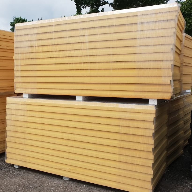
The standard external board size is 1200 × 2400 mm. Set out joints using the cover width of the selected edge profile. This is 1200 mm for BASIC, 1185 mm for TOP and 1190 mm for MASTER. Draw the support footprints on this layout before cutting boards around service penetrations.
Drainage and maintenance access
Long base rails on a flat roof can cross the drainage path to an outlet. Check the position of the rails, overflows and service penetrations on the roof falls plan. Specify protection compatible with the membrane at each foot and detail any seals required.
A technician needs access to the service panel and space to replace parts. Mark a maintenance route and a temporary set-down area for removed components. Gas-tight PIR facings neither seal penetrations through the roof covering nor protect the membrane from the edge of a tool.
Information the installers need
Give the installers a coordinated drawing of the unit, base and roof layers, dimensioned from fixed grid lines. Mark the outlets, fixing points and access zones. If a foot has to move, have the designer reassess its bearing before the detail is covered.
For handover, record the boards, load spreaders, fixings and waterproofing work actually installed. A photograph taken before placing the equipment helps locate board joints and verify membrane protection later. Keep the as-built drawing for a future replacement unit or a change to the PV layout.

Free quote
What to include in your enquiry
Tell us how you plan to use the material, the dimensions and the quantity you need. Include the thickness, grade or variant name, along with the delivery town or your preferred collection branch. For a specific product, add its name or a link to the product page. We will reply to the email address you provide to discuss availability and the terms of your order.

Read next

For IKO enertherm ALU TG, choose the laying direction before cutting the first row. The tongue on one factory edge must slide…
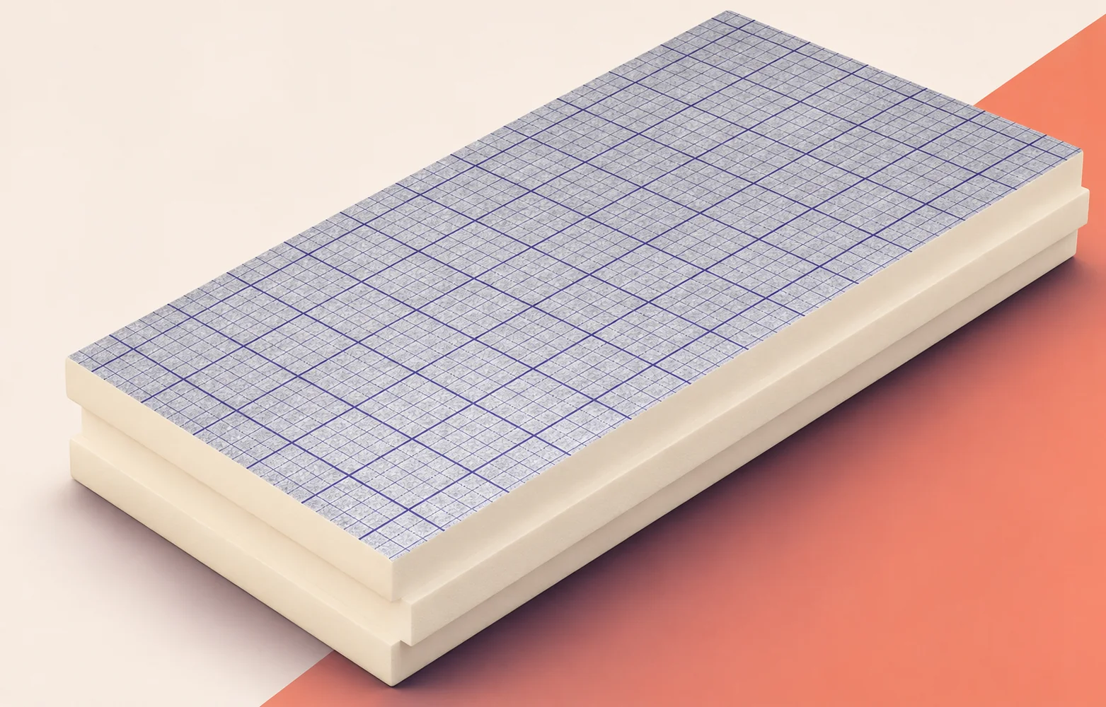
Installing swissporPIR Alu above the rafters raises the roof covering relative to the eaves, roof windows and chimney. On a large slope,…
A doorway between a corridor and a heated room reveals whether the floor build-up fits between the structural slab and the door…
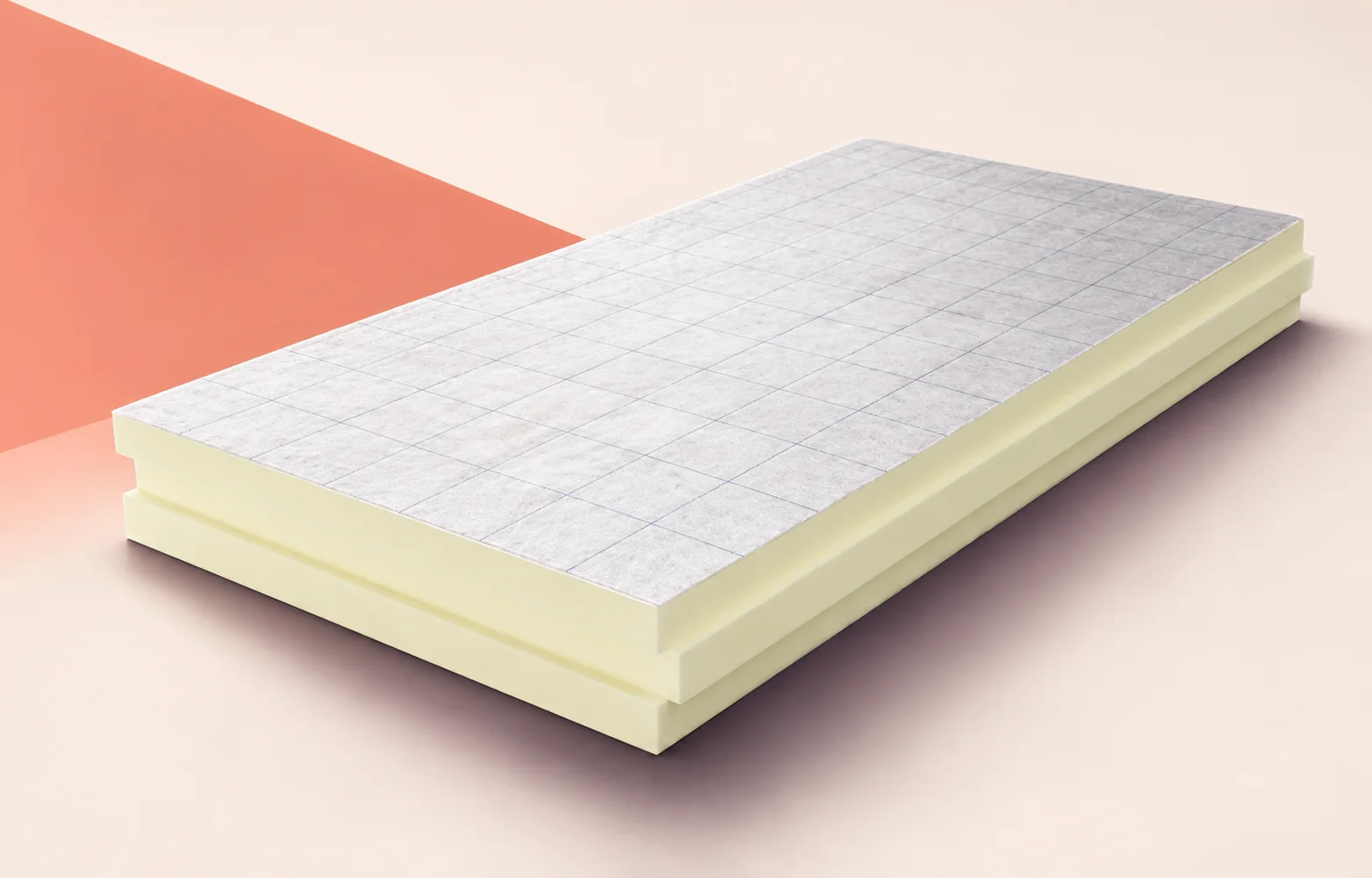
When refurbishing an industrial building with low door thresholds, measure the height from the substrate to finished floor level before choosing termPIR…
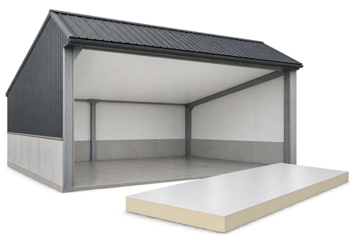
An internal ceiling can separate a heated or climate-controlled room from the roof void. In a cattle shed or warehouse, its appearance…
Intermittent use makes warm-up time, moisture on arrival and running costs between visits especially important. It calls for a different plan from…
When swissporPIR Alu arrives for several industrial buildings, assign each pallet to a specific work area before lifting it to the roof.…
When specifying BauderPIR FA-TE on a service terrace above a heated room, start with a section through the threshold and nearest outlet.…