






Wind loading on large fibre-cement roofs
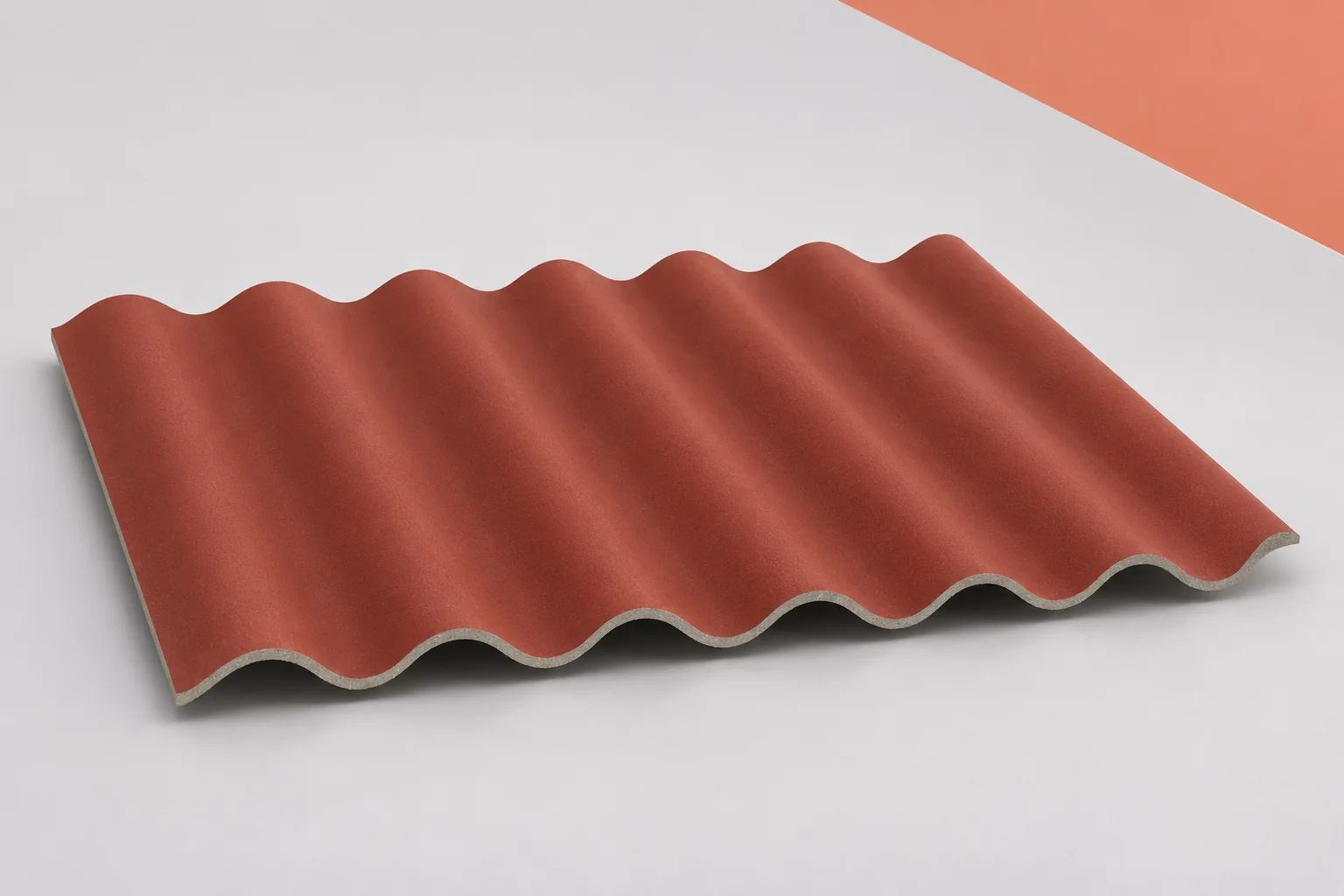
Fibre-cement roofing
Wind forces vary across a large roof. The corners, edges, height of the building and openings in its walls all influence the loads. Select fibre-cement sheets, supports and fixings together for the particular building. The weight of an asbestos-free sheet alone tells you little about wind resistance. Follow the load path from the roof surface through the frame to its anchorage. Open terrain, neighbouring buildings, height and topography affect exposure. Trees or temporary stacks of materials may provide little shelter over the life of the roof. Base the design on lasting site conditions and the applicable design rules.
In this guide
Record the building’s exposure
An extension may change the exposure of the original roof. A similar building next door cannot take the place of a calculation. Differences in wall openings, geometry and height can change what the connections must resist. Collect this information before ordering the covering.
Check uplift as well as downward pressure
Wind suction can lift the sheets away from their supports. The fasteners and the material around the holes must resist this force. A sheet’s ability to carry downward pressure addresses a different load case. Select the fixings for uplift, without relying on the sheets’ own weight to hold them down. Check the purlin connections to the main frame as well. Strengthening a sheet fixing leaves any weaker connection farther along the load path exposed. Show the entire load path in the design and identify the points requiring special details.
Design the edge and corner zones
The fixing pattern for the middle of a slope may be unsuitable at its edges. Follow the design and the installation instructions for each zone, including support for the outermost sheets and the edge trim. Allow for fixing positions in the cutting plan before delivery. A narrow offcut at the eaves or verge may leave too little room for a sound fixing. Adding screws wherever there is space after installation is no substitute for a planned layout. The positions, spacing and engagement with the sheet must suit the specified system.
Account for open doors
Internal pressure contributes to wind loading on the envelope. Tell the designer which doors and openings are used, including doors left open for most of a shift. A roof over an open-sided shelter experiences different conditions from a roof on a tightly enclosed building. This affects the choice of sheets and fixings. Enlarging a doorway, removing a wall section or changing how the building is operated may warrant reassessment of the original design.
Size fixings to protect the sheet
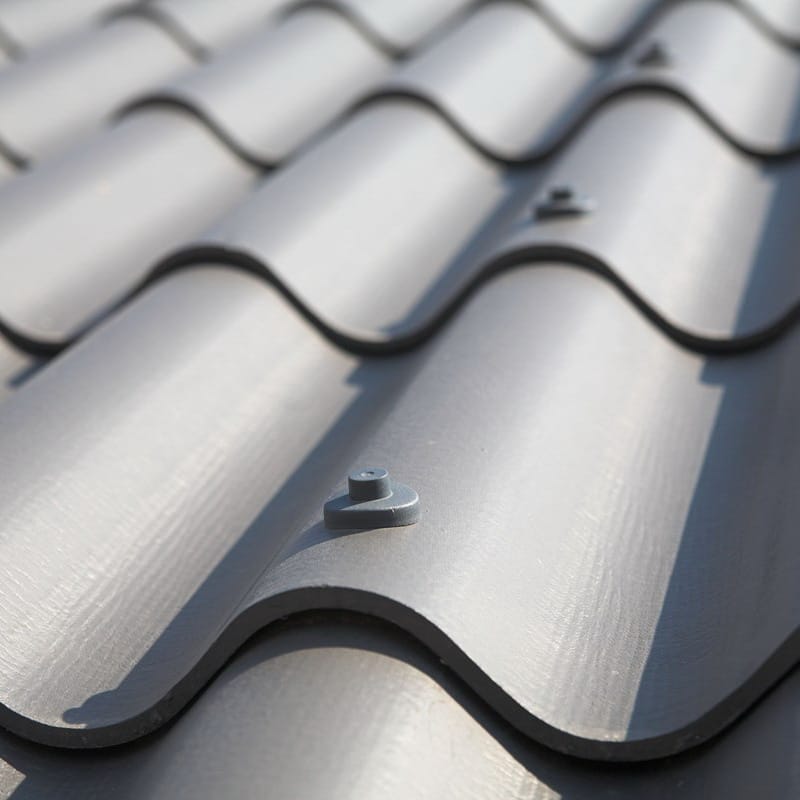
A connection’s load capacity does not come from tightening it as hard as possible. Excessive compression can damage the sheet or seal. Use the specified hole and matching components. Check the support material, its thickness and the fastener’s corrosion resistance. A longer fastener cannot automatically make up for an unsuitable one. Where extra fixing points are necessary, have their positions designed. At handover, inspect the material around the holes. Cracking during installation can weaken a fixing before the first storm.
Allow for rooftop equipment
PV arrays, equipment and rooftop structures change local airflow, introduce loads and need their own load paths. Transfer bracket loads into the structure so fibre cement continues to serve as the covering. Consider where debris may accumulate and whether connections will remain accessible beneath the equipment. Before retrofitting equipment, assess the condition of the existing sheets, fixings and supports to establish how the new structure can be attached.
Inspect the affected area after high winds
Displaced flashing or a cracked sheet may indicate wider damage. Arrange safe inspection access without walking on the covering. Examine adjacent fixings and the underlying structure as well as the sheet where water entered. If the wind load exceeded what the arrangement could withstand, repairing only the leak may leave other weaknesses. Use the design and as-built records to check how the roof was installed and whether use of the building has changed since then.
Give the designer the location, building geometry and operating pattern of its openings. Specify sheets, fixings and supporting structure as parts of a single load path.

Free quote
What to include in your enquiry
Tell us how you plan to use the material, the dimensions and the quantity you need. Include the thickness, grade or variant name, along with the delivery town or your preferred collection branch. For a specific product, add its name or a link to the product page. We will reply to the email address you provide to discuss availability and the terms of your order.
Read next
A factory roof is exposed to conditions set by the production process as well as by the weather. Temperature, steam, dust and…
Installing photovoltaics changes the loads on an industrial roof. Before choosing a mounting system, have the sheets, purlins, fixings and primary structure…
An industrial building’s envelope must keep out the weather and maintain the conditions required inside. Corrugated fibre cement sheets can form the…
Corrugated fibre-cement sheets and insulated sandwich panels can both roof an industrial building. They provide different parts of the roof assembly. Fibre…
When steel purlins support corrugated fibre-cement roofing, design the sheets, fasteners and steelwork together. Check the design loads, distances between supports and…
Where a corrugated fibre-cement roof meets a sandwich-panel wall, the joint has to shed water, maintain any required insulation and accommodate movement.…
Every penetration interrupts the roof covering. Plan pipes, vents and brackets with the fibre-cement sheet layout before delivery. The services contractor needs…
Daylight can improve working conditions in an industrial building if it reaches the right places. Lay out the rooflights in relation to…